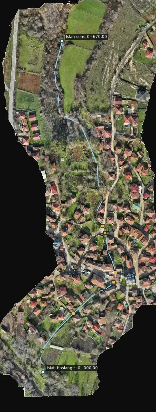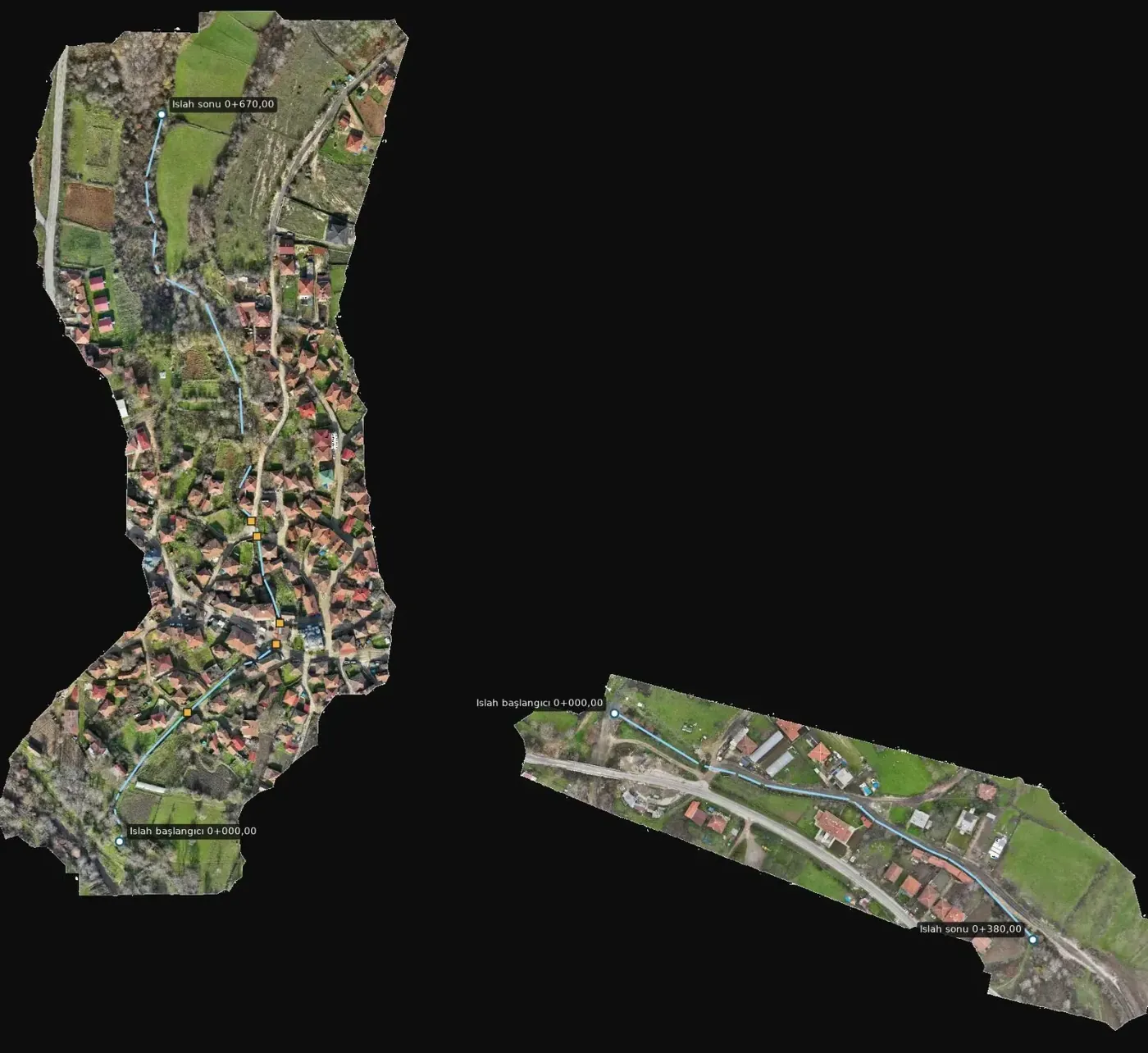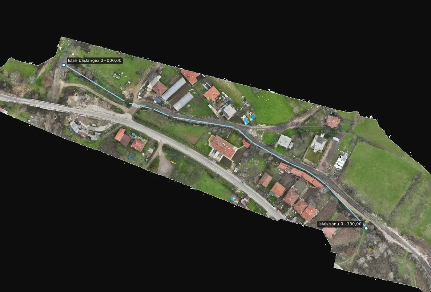
What the project needed
An urban channel scheme is designed on profiles: the longitudinal one to fix gradients and the cross sections to size the channel and check the existing culverts. Between houses, walls and private accesses, the challenge is to get those sections without occupying the street for days.
Why high resolution photogrammetry and not LiDAR
Where a stream runs through a village the vegetation is usually kept down and the ground is visible, so 1.9 cm photogrammetry gives enough density to cut reliable sections from the surface model. As a general rule LiDAR pays off under continuous vegetation; here the priority was detail on edges, walls and culverts, where imagery reads better. Sections were extracted from the model every 10 m along the defined axis.
What was delivered
The documents a channel improvement needs, ready for sizing the section.
-
Orthophoto
Current background of streets, fences and banks for the design plan.
-
Alignment and culvert drawing
Channel axis and position of existing structures to keep or replace.
-
Longitudinal and cross sections (NetCAD)
Gradients, depths and sizing of the new channel.
-
KMZ file
Locating the alignment in a geographic viewer for meetings with the council.
If you have a similar project in Spain
Ask for the axis and profiles in ETRS89 and your UTM zone, set the section spacing your hydraulic calculation requires, and request profiles as DWG or DXF plus a georeferenced orthophoto. To quote, we need the approximate axis of the channels as KMZ, the length of each branch and the strip width to document on each side.