What the project needed
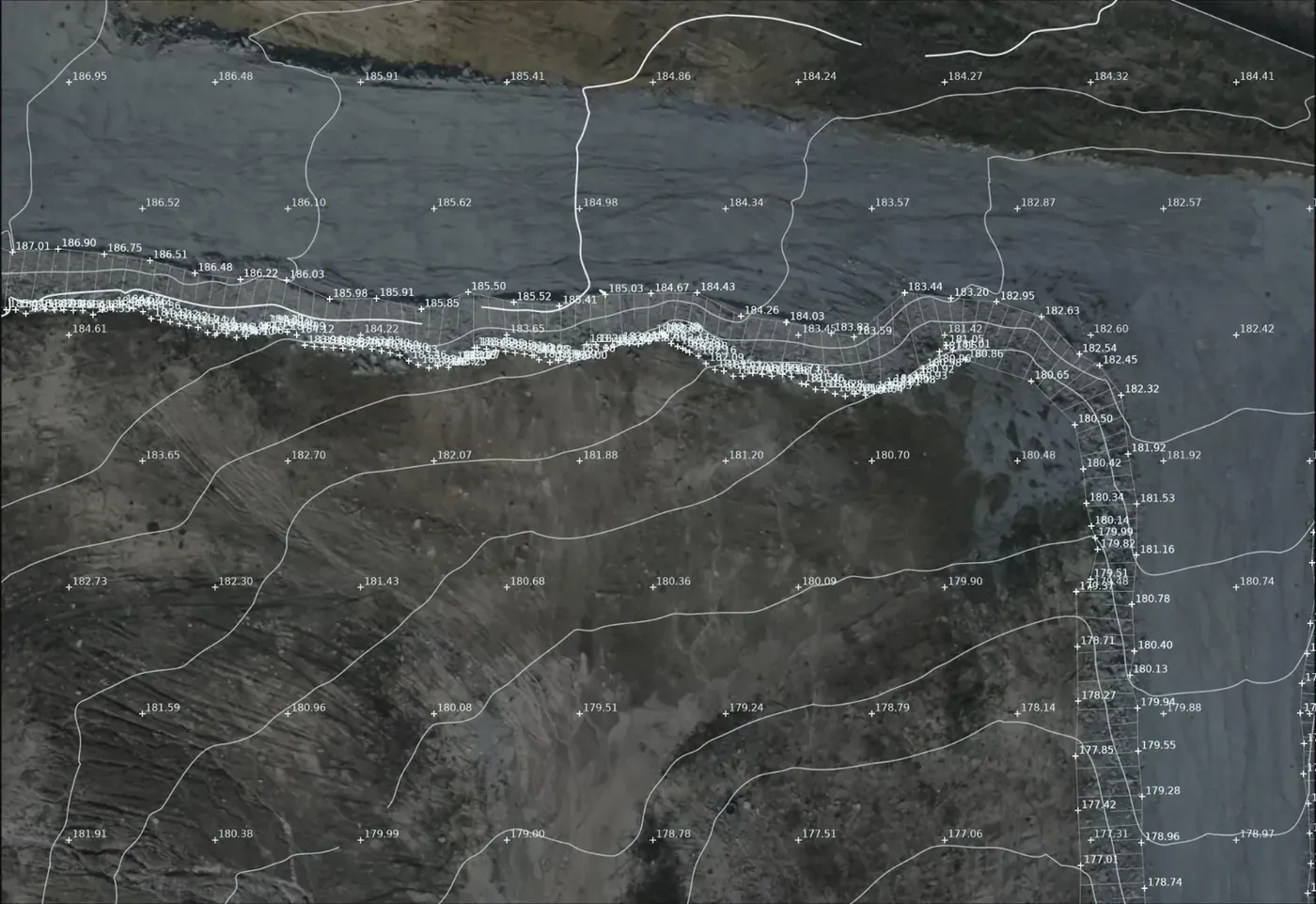
A spot height plan reflecting the real state of the plot, not an old survey, and a georeferenced image on which to fit the building and its accesses. On urban and edge of town land the ground changes with every neighbouring job, and an outdated level is paid for in foundations and site works.
Why photogrammetry tied to ITRF
The value of a spot height plan lies in its reference system: if it sits in the official frame, any later GNSS setting out will agree with it. Here the photogrammetric block was referenced to ITRF, the frame Turkish official mapping works in, and the heights were read off the surface model. As a general rule, on open plots photogrammetry gives the point density a design needs without resorting to LiDAR.
What was delivered
Two files the architect can start drawing on the same day.
-
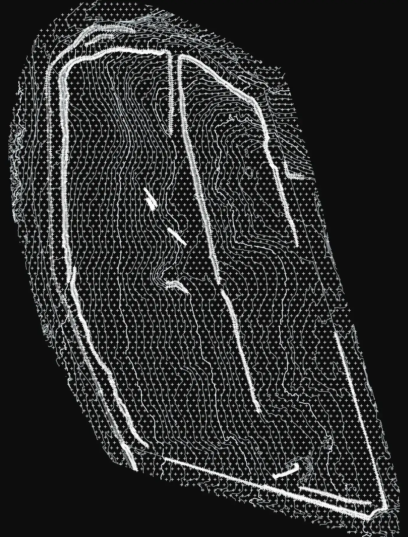
Spot height drawing (NetCAD, DWG)
Ground levels for siting the building, accesses and drainage.
-
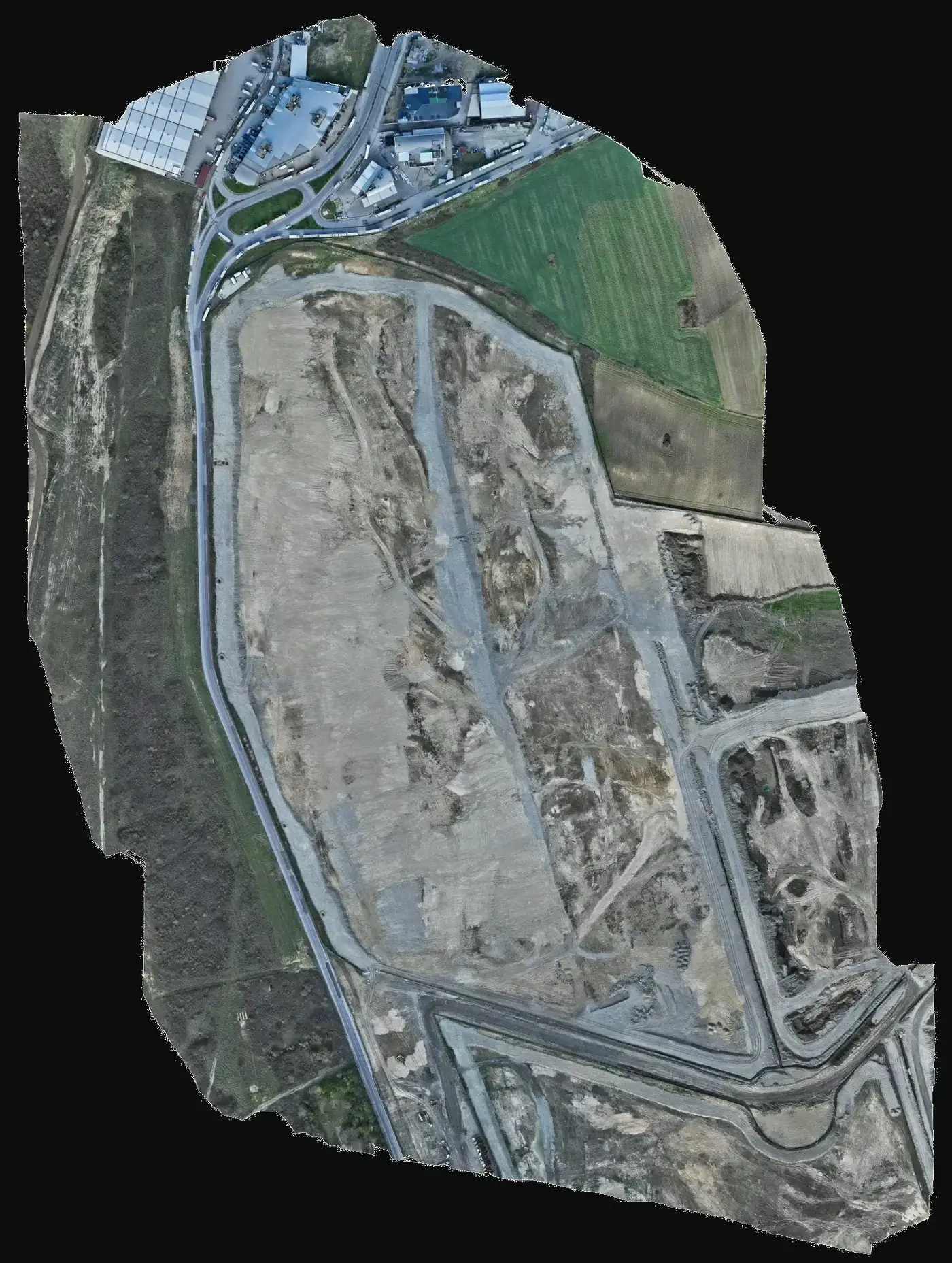
Orthophoto (ECW)
Current georeferenced image for fitting the design and checking boundaries.
If you have a similar project in Spain
The equivalent here is to ask for the plan in ETRS89 and your UTM zone, with heights as DWG or DXF and the orthophoto as GeoTIFF or ECW with its GSD stated. Also confirm which height datum is used. To quote, we need the plot perimeter as KMZ, the intended use of the plan and whether buildings or vegetation hide the ground.