The specific problem
The road project's existing mapping was complete except for one forested stretch. Without ground heights there, the vertical alignment cannot be fixed and earthworks cannot be calculated, and surveying it with GNSS under dense canopy is slow and suffers from poor signal.
Why LiDAR was the only sensible route
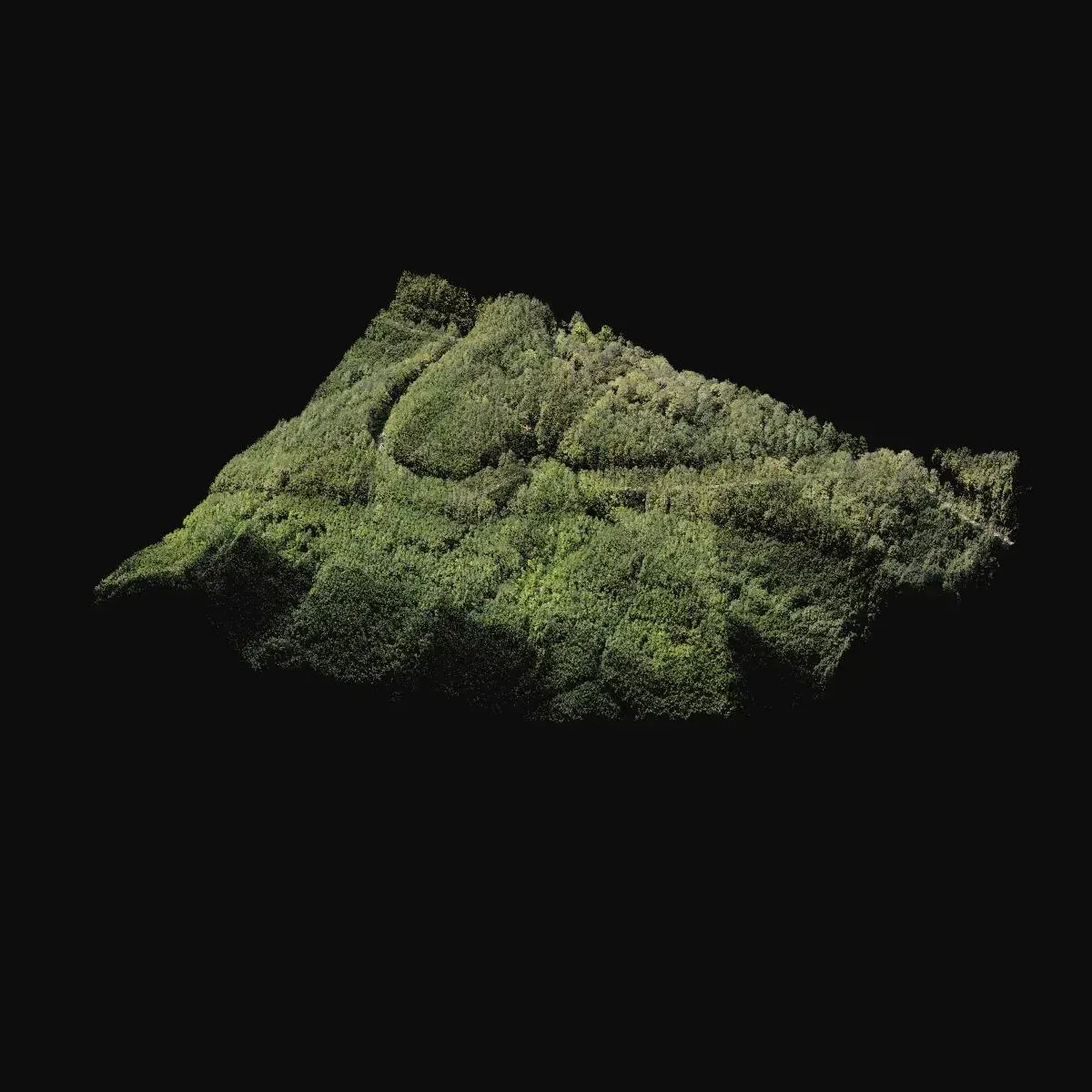
Under trees, photogrammetry returns the canopy, not the terrain. LiDAR sends pulses that pass through gaps in the foliage and records several returns; the last ones belong to the ground. Here a Zenmuse L2 scanned the stand and the echoes that had passed between the trees to the soil were isolated, which is where the terrain model comes from.
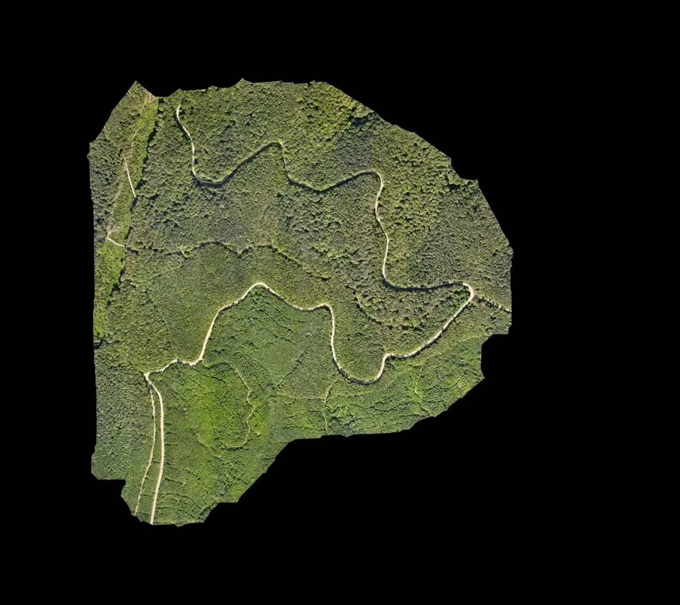
The true orthophoto, built on the surface model, removes the lean of treetops and tall objects that a conventional orthophoto shows, so it sits on the drawing without offset.
What was delivered
Three files that drop straight into the existing road design.
-
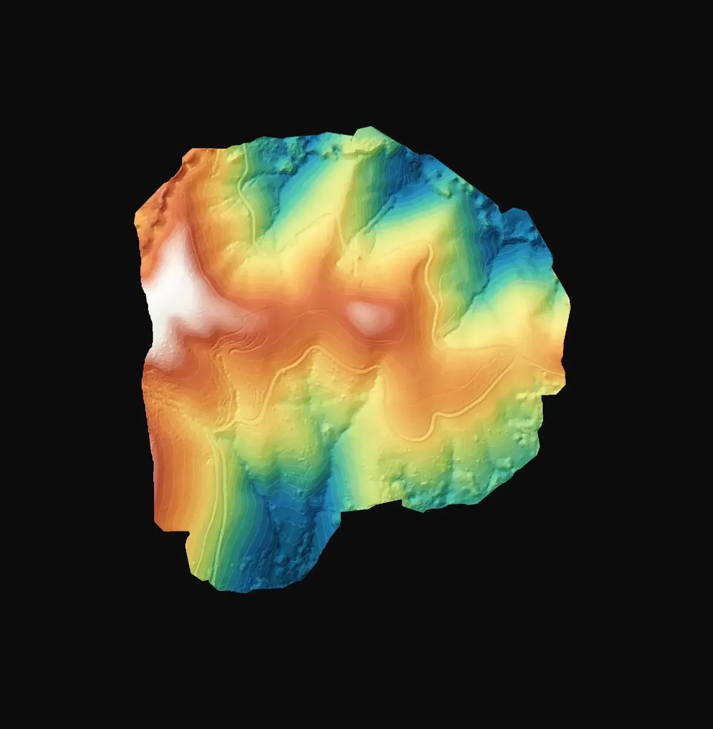
Terrain model
Ground heights under the trees for the vertical alignment, sections and earthworks of the stretch.
-
True orthophoto
Offset free background for drawing the alignment and checking limits.
-
DXF drawing
A layer that merges into the road plan in any CAD package.
If you have a similar project in Spain
If your mapping has gaps under vegetation, ask for the terrain model in the same system as the rest of the project (usually ETRS89 and the local UTM zone) and the classified cloud as LAS or LAZ so you can review the ground and vegetation split. To quote, we need the polygon of the gap, the density of the stand and the drawing formats your team uses.