What the project needed
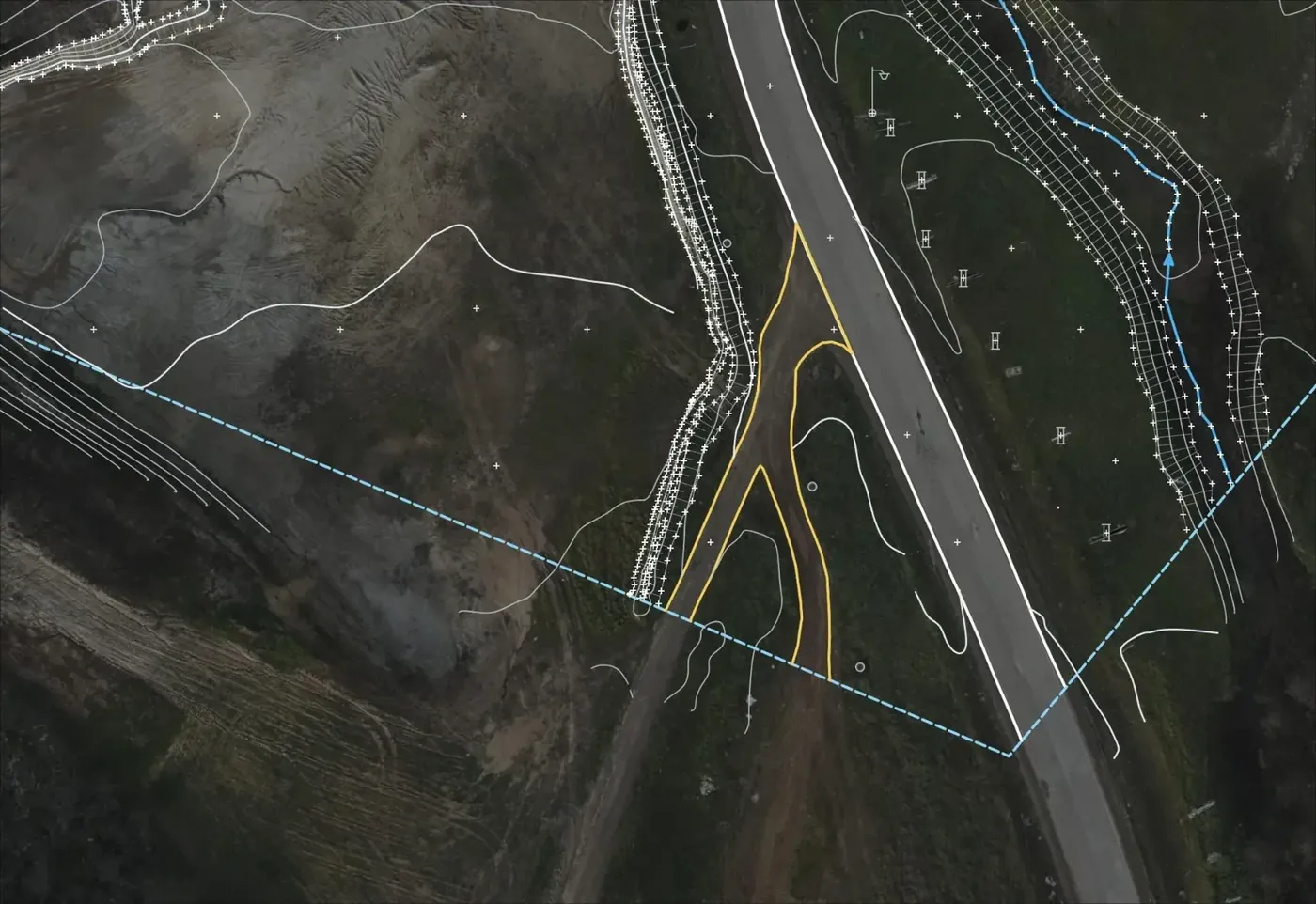
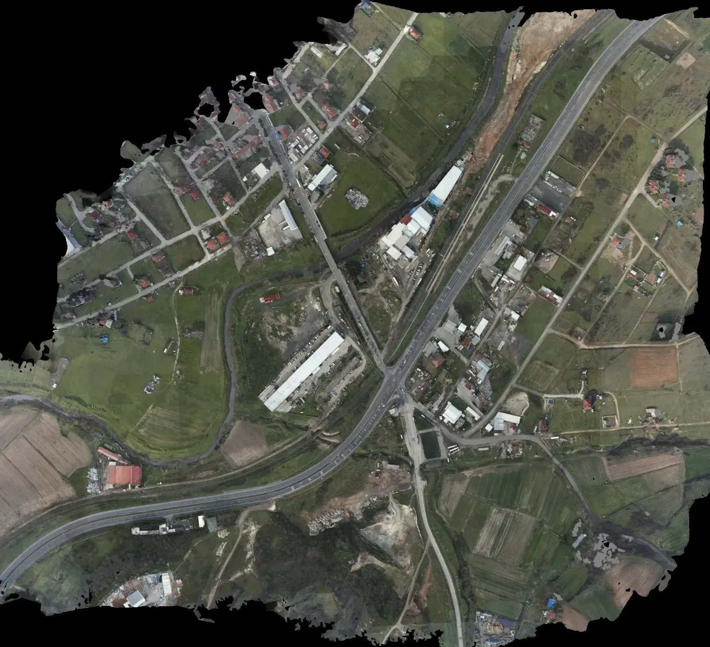
A junction needs more than a terrain model: carriageway edges, ditches, culverts, fences and visible utilities have to be drawn, and at the same time a continuous surface is needed to fit grades and ramps. The brief covered both over about 113 ha.
Why imagery and LiDAR together
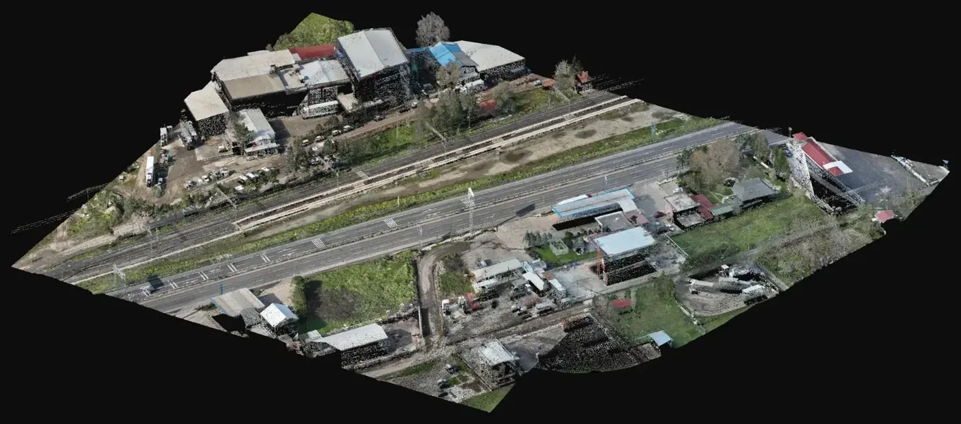
The 4.7 cm orthophoto makes the linear features of the existing road easy to identify and draw; the LiDAR cloud gives heights in ditches, embankments and long grass where imagery loses the ground. The drawings were compiled from both sources, planimetry from the orthophoto and heights from the cloud. As a general rule, on road corridors with vegetated verges this pairing cuts the follow up fieldwork.
What was delivered
Formats chosen for the usual workflow of a highway design office.
-
Topographic map (NetCAD, DWG)
Planimetry and heights of the junction for the geometric design.
-
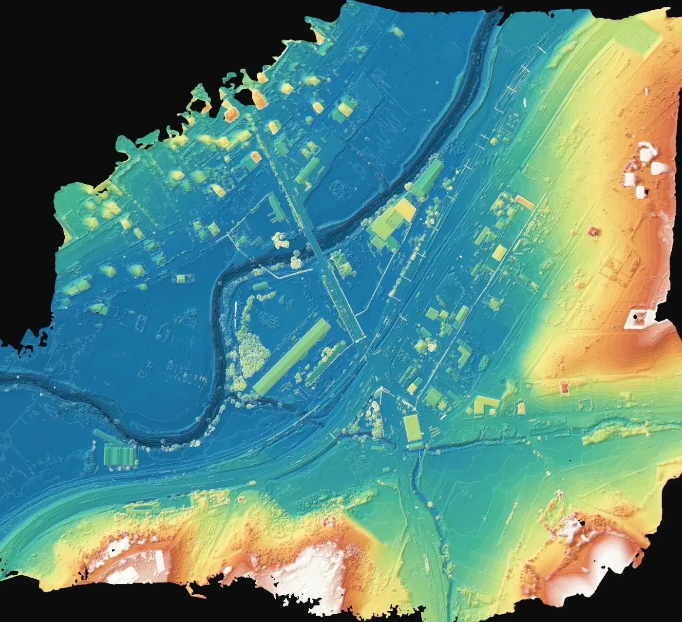
Triangulated model (TIN) and contours
Surface for grades, sections and earthworks of the ramps.
-
Surface model
Checking clearances and above ground features.
-
KMZ file
Quick review of the extent in a geographic viewer without CAD software.
If you have a similar project in Spain
Ask for the plan in ETRS89 and the local UTM zone with separate layers for planimetry and heights, the TIN or terrain model in a format your alignment software reads, and the cloud as LAS or LAZ. To quote, we need the extent as KMZ, the minimum GSD in your specification and the list of features that must appear in the drawing.