What the project needed
To improve a stream the hydraulic engineer needs the channel bed, the banks, the existing culverts, the walls and the roads running alongside, all in one coordinate system. Much of that sits under riparian vegetation, which is exactly where image based methods fail.
Why LiDAR with ground control
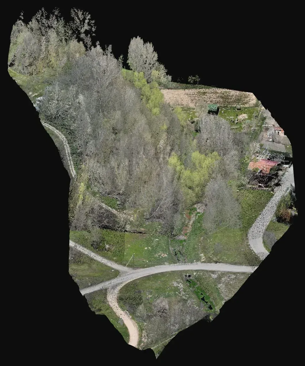
Drone LiDAR records several returns per pulse and lets the ground under riparian vegetation be separated, which a conventional orthophoto cannot offer. The cloud was tied to ground control points measured on site so that channel heights can be compared with any later measurement. As a general rule, on narrow tree lined corridors LiDAR avoids wading sections by hand and shortens the time in the field.
What was delivered
Four products covering planimetry, alignment, imagery and relief of the corridor.
-
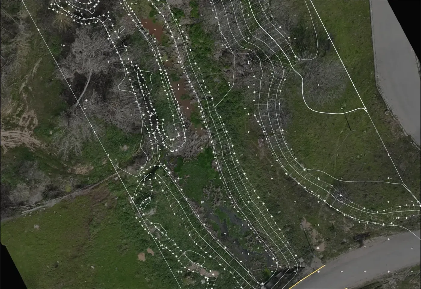
Topographic drawing with roads, culverts, walls, banks and contours
Planimetric and height base for the channel improvement design.
-
Alignment drawing
Channel axis on which profiles and cross sections are defined.
-
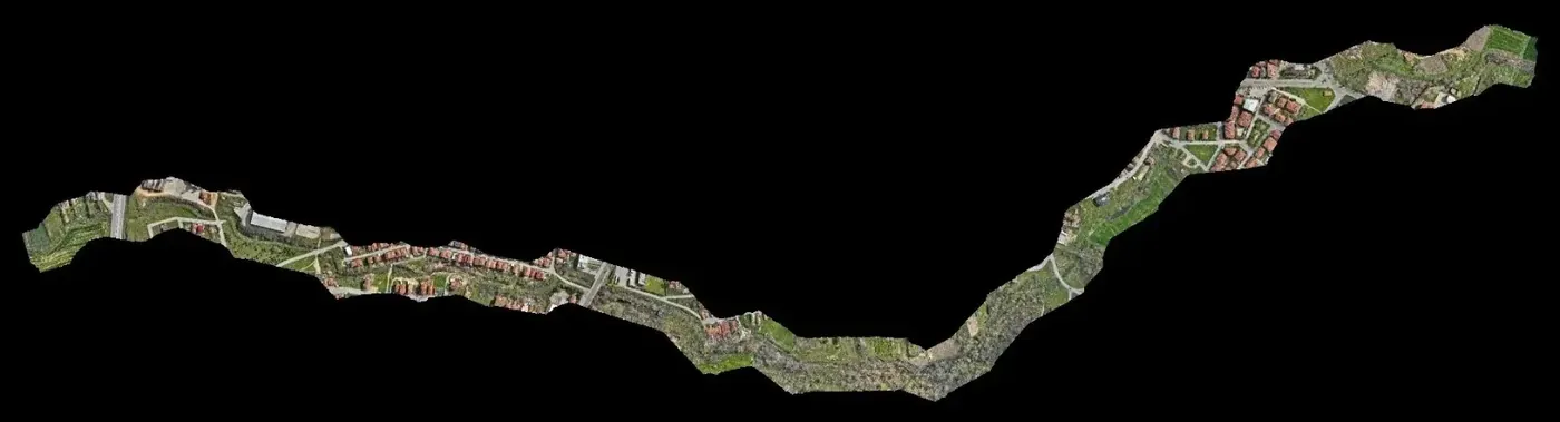
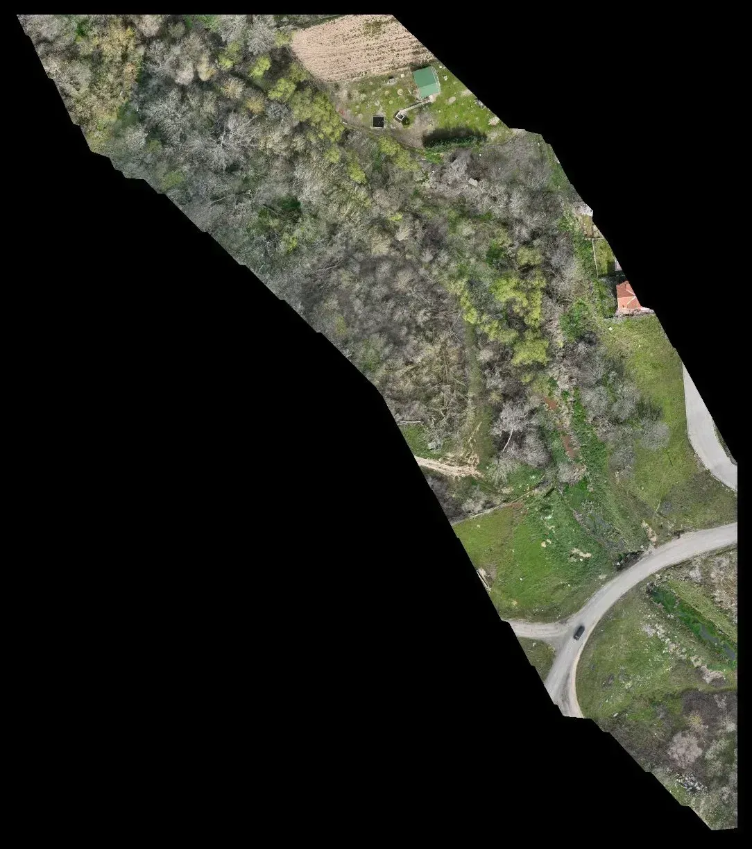
2.1 cm orthophoto
Georeferenced image for spotting outfalls, erosion and land use on the banks.
-
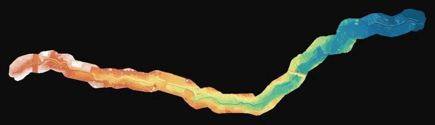
Terrain model
Hydraulic calculation, flood extent and earthworks quantities.
If you have a similar project in Spain
Ask for the drawing and terrain model in ETRS89 and the UTM zone of your site, the classified cloud as LAS or LAZ, and define which structures must be drawn (culverts, walls, fords). To quote, we need the stream centreline or corridor polygon as KMZ, the strip width on each side and the state of the vegetation on the planned date.